- Material
- Steel
- EN 1.2510 Equiv.
- Stainless Steel
- EN 1.4037 Equiv.
- EN 1.4301 Equiv.
- Surface Treatment
- No Treatment
- Hard Chrome Plating
- Hard Chrome Plating
- Heat Treatment
- [D] Diameter (Mounting Side)(mm)
- [P] Diameter (Head)(mm)[10-16/0.01mm unități]
- [M] Diameter (Screw)(mm)
- 6
- [L] Length (Pin)(mm)[10-24/1mm unități]
- [B] Length (Head)(mm)[5-20/0.1mm unități]
- Dimension Configurable Type
- CAD
- 2D
- 3D
- Est. zile de expediere
- Toate
- În 6 zile lucrătoare
Locating pins / round / small, chamfered flat head / internal thread / h6

Cod piesă:
candidați nedefiniți.Desen de ansamblu și tabel de specificații
Back to the Category Locating Pins / Positioning Pins / Centring Pins
Available dimensions and tolerances can be found under the tab More Information.
| Material No. | Material | Surface Treatment | Hardness | Type | ||
| P Selectable | P Configurable | P, L, B Configurable | ||||
| EN 1.2510 Equiv. | - | Treated Hardness: 60 ~ 63HRC | JPDSTB | JPDSTC | FPDSTC | |
| EN 1.2510 Equiv. | Hard Chrome Plating | Treated Hardness: 50 ~ 55HRC Plating Hardness: 750HV ~ | - | - | GFPDSTC | |
| EN 1.4301 Equiv.* | - | - | SJPDSTB | - | SFPDSTC | |
| EN 1.4037 Equiv. | - | Treated Hardness: 50 ~ 55HRC | - | CJPDSTC | CFPDSTC | |
Further specifications can be found under the tab More Information.
| Part Number | - | P | - | L | - | B |
| JPDSTC6 FPDSTC6 | - - | 4.00 P4.00 | - | L10 | - | B5.5 |
Selection details of receiving pins/locating pins/ centering pins
- Material: steel, stainless steel, aluminum, plastic
- Coatings: burnished, nickel-plated, hard chrome-plated, polished, hard chrome-plated and polished, clear anodized
- Heat treatment: carburized, quenched
- ISO tolerances mounting side: m6, n6, p6, g6, h6, h7
- Head diameter: 1 to 30 mm
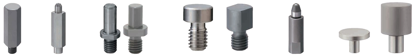
- Basic form: wide head, narrow head, cylindrical, with collar, with hole, with flange, double guide
- Assembly side form: fit, external thread, internal thread, circumferential groove, notch, flat surface
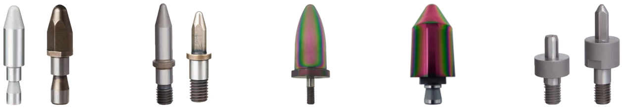
- Head shape: round, diamond-shaped (sword shape), triangular
- Tip shape: fastened, rounded, conical, round, spherical, flattened, ball attachment, projectile-shaped
Description/Basics
centering pins are used to fix the position and limit the degrees of freedom of the objects to be positioned. The precisely manufactured centering pins enable highly precise positioning of the assembly parts. centering pins can position objects as side stopper or center them by insertion. This allows positioning them in the X, Y and Z axes.
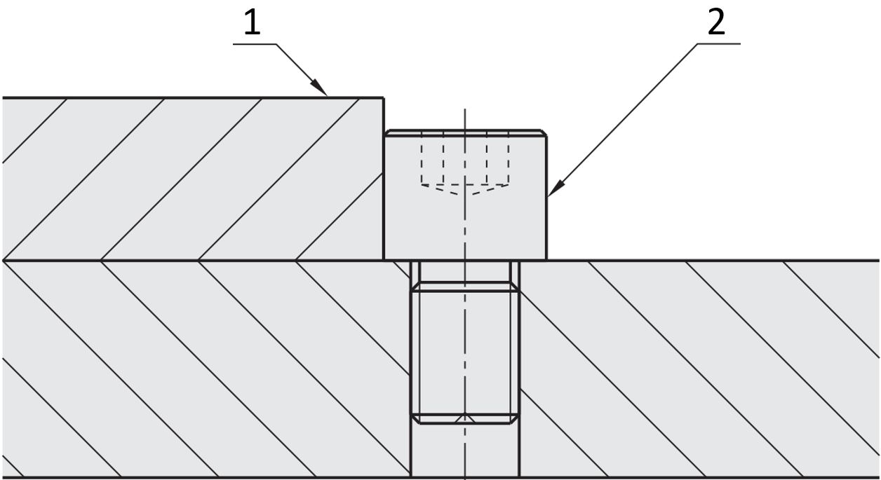
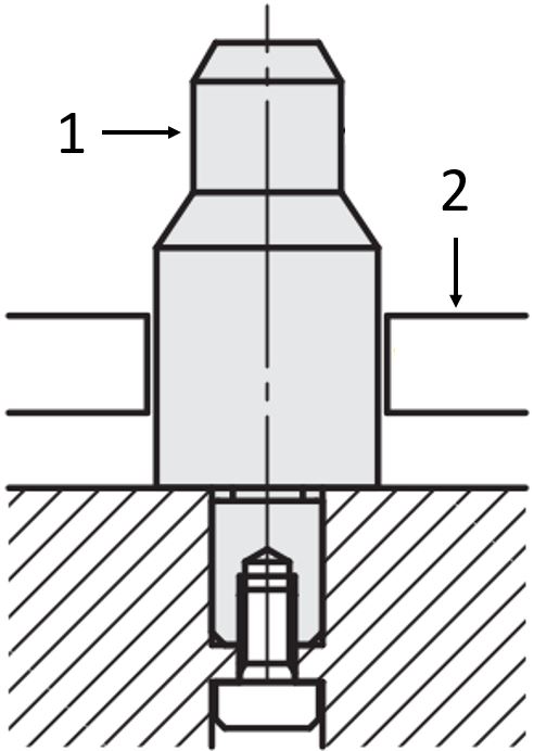
Application example: centering pin as work piece stopper - (1) work piece, (2) threaded receiving pin
A straight centering pin is only sufficient for the X and Y axis to determine the position of an assembly part. In order to additionally adjust the position in the Z axis, a centering pin with a collar can be used. This combination can reduce the variety of components, since there is no need for an additional support pin.

Application example for a centering pin with collar
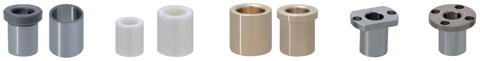
In most cases a plug-in connection uses a centering pin to protect the work piece or the application during multiple joining and positioning. The centering bushings protect the component from unwanted wear, especially if the objects to be placed are made of a soft material. Therefore, positioning bushings make an application more maintenance-friendly. Wear should always be considered when planning an application. The material and the surface coating of centering pins should be selected according to the application.
Application example for a centering bushing - (1) centering bushing
Function
If objects cannot be placed straight, but slightly inclined on centering pins, a round or chamfered head shape can be used. This helps ensure that the objects do not jam with the centering pins and the process runs smoothly. A round or chamfered head shape is also advisable for applications that are highly repetitive (cycles).
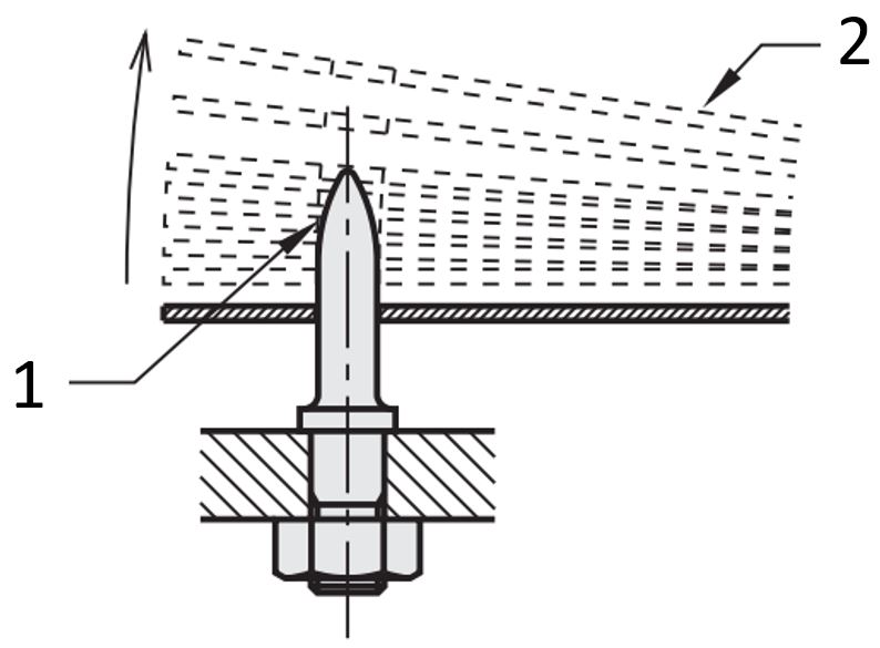
Application example for an inclined infeed - (1) centering pin rounded head, (2) workpiece
For the highest possible positioning accuracy centering pins should be used in pairs as much as possible. The respective distance between the centering pins also influences the position accuracy. If it is chosen large, it can improve the accuracy of the object’s positioning. If there is a large distance between the centering pins (B), one of the locating pins should have a diamond-shaped head (sword pin), since a sword pin almost prevents tilting. The use of a third centering pin in an L-shaped (triangular) arrangement may improve the positioning accuracy even further. In order to ensure that the centering pins are not interchanged, centering pins with different diameters should be selected.
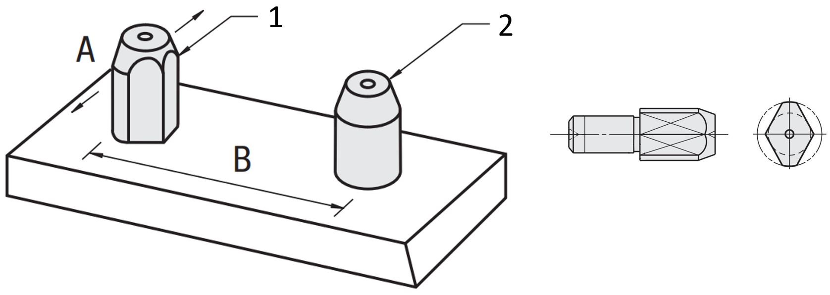
Application example for a sword pin - (1) sword pin (diamond-shaped), (2) centering pin (round)
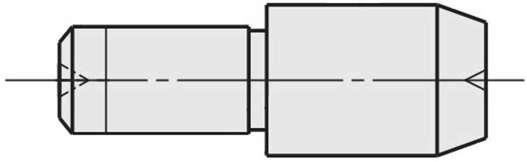
MISUMI offers various mounting variants for centering pins in order to keep applications maintenance-friendly. Centering pins with internal threads can be interchangeably fastened with a screw through the mounting plate from underneath. If access to the underside is difficult, a centering pin or sword pin with external thread can be used. The assembly and disassembly of the centering pins can thus be easily designed by means of the various mounting versions.
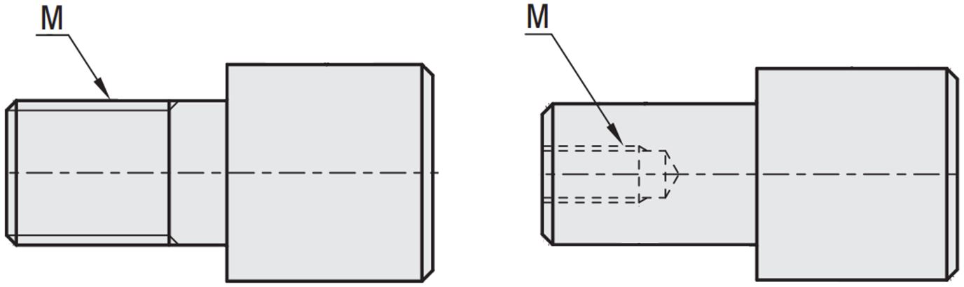
Centering pin with external thread/ centering pin with internal thread
Areas of Application
centering pins are used in work piece carriers as well as the highly accurate positioning of components in test benches. centering pins enable highly precise positioning of objects with all degrees of freedom, thanks to the versatile and highly configurable shapes. The wide variety of MISUMI centering pins offers a suitable shape for every application. Centering pins are used for thin sheets as well as for heavy and complex components. This means that centering pins can be used across almost all industries of plant engineering and mechanical engineering. In many applications, centering pins are indispensable, as they enable a highly accurate positioning of the components.
Materials
The MISUMI centering pins are available in the following materials: steel, stainless steel, aluminum, plastic . Pins made of steel and aluminum are available in both hardened and coated versions. With a high number of cycles, the use of a hardened material is recommended, as these have a higher wear resistance.
Corrosion resistance
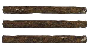
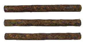
The following salt water spray test was performed on the raw material (see table) of the centering pins and mounting pins. Corrosion resistance was determined based on the test times of 48 and 96 hours.
| EN 1.4305 equivalent | EN 1.4301 equivalent | EN 1.4125 equivalent | EN 1.2510 equivalent |
Before the test |
|
|
|
|
48h |
|
|
|
|
96h |
|
|
|
|


Shear load in comparison
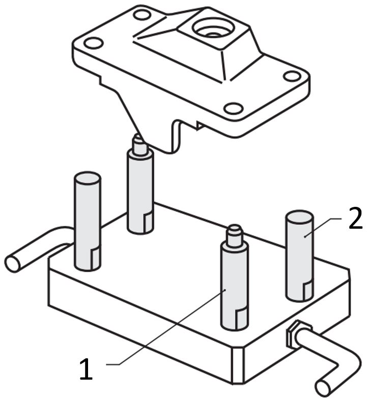
During a test procedure, the shear load of a centering pin was tested with different steels. The tested centering pin was based on JPBB8-10 and was tested for a shear load in a device (see figure). The following table lists the test results for comparison purposes.
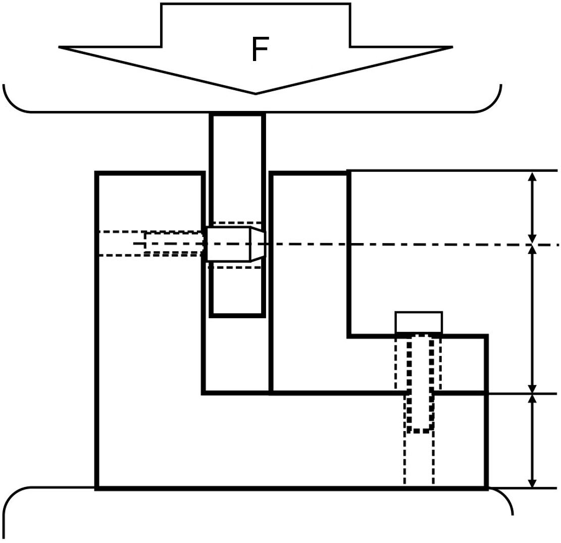
Application example for the shear load of receiving bolts
Materials | Shear load | Hardness |
EN 1.2510 equivalent | 65 kN | 60 ~ 63 HRC |
EN 1.4301 equivalent | 27 kN | 10 ~ 20 HRC |
EN 1.4125 equivalent | 56 kN | 50 ~ 55 HRC |
Coatings
MISUMI locating pins are available in burnished, hard chrome-plated or anodized to protect them from corrosion. Locating pins that have to withstand many cycles can be hard chrome-plated. The hard chrome plating provides a high surface hardness and provides the locating pin with high wear resistance. The selectable polished surface also ensures good surface roughness of the cylinder pins and helps to achieve good sliding properties. Aluminum locating pins are translucent anodized to protect them from corrosion and wear.
Dimensions
Locating pin with wide head

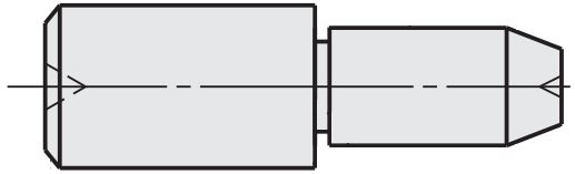
Locating pin, two-stage
Locating pin with narrow head
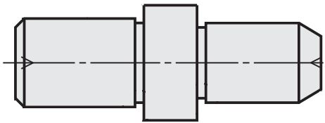
Locating pin with collar

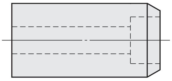
Cylindrical locating pin
Locating pin with fastening hole
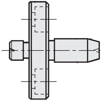
Flanged locating pin

Conical flanged locating pin
Maintenance
To facilitate maintenance for the centering pins, V-shaped wear grooves can be applied to the centering pin. The 0.2 mm deep grooves serve as a wear indicator of the usable surface. This makes the visual wear on the centering pin comprehensible and makes it easier to maintain the accuracy of the device. The wear grooves of the centering pins are only available with hardened and round centering pins.
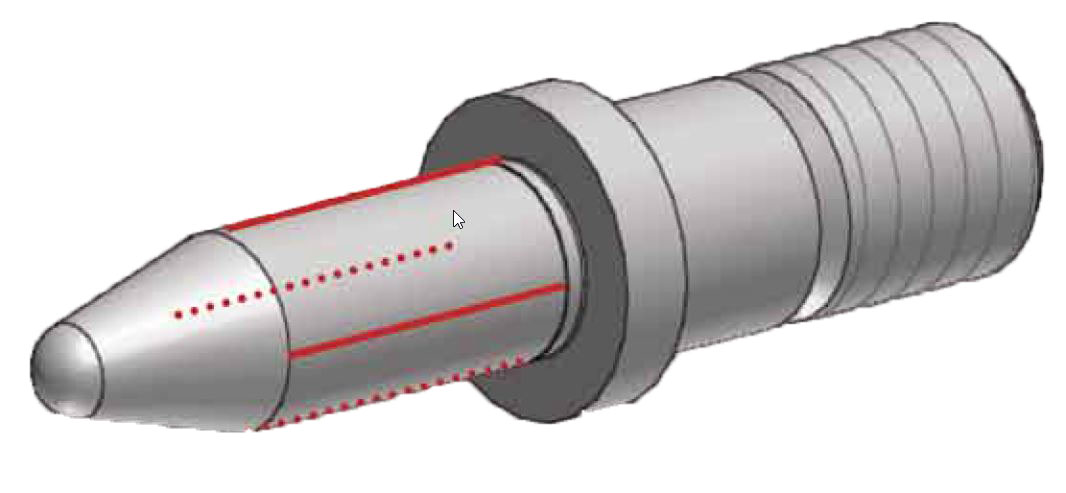
Example of a centering pin with wear groove (red)

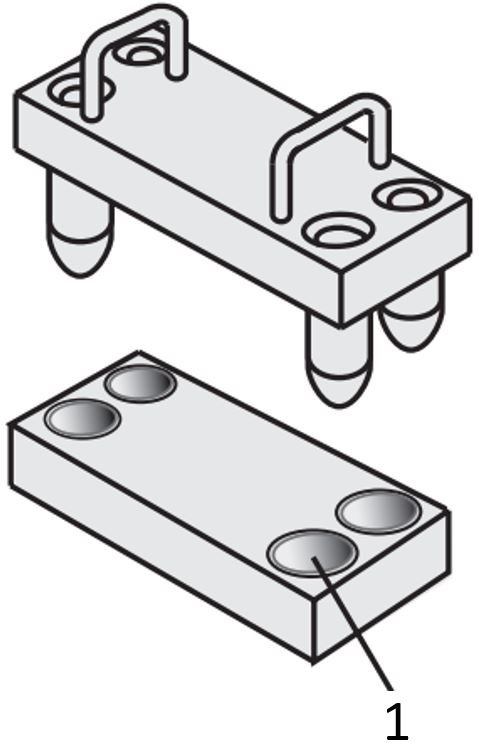
centering pin/ centering bushing with collar - (1) centering pin, (2) centering bushing

centering pin/ centering bushing - (1) centering pin, (2) centering bushing, (3) mounting plate
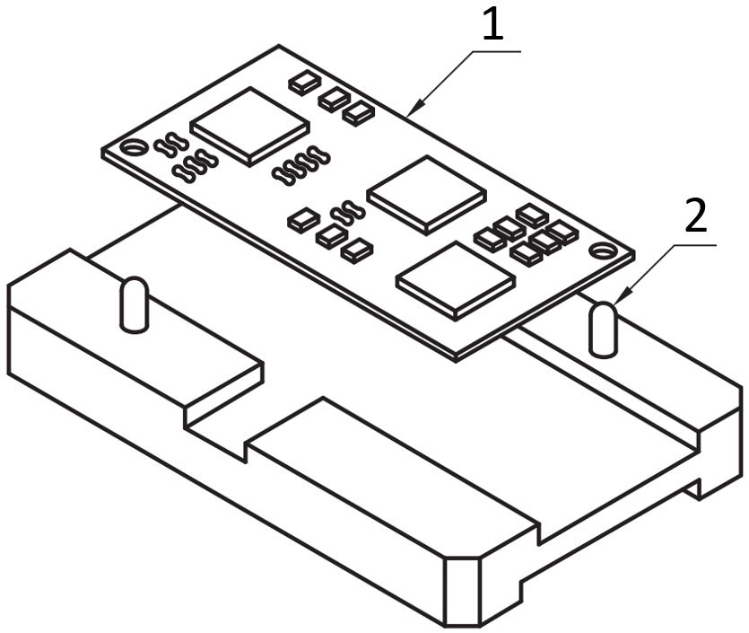
Workpiece carrier with centering pin - (1) circuit board/printed circuit board, (2) centering pin
Workpiece carrier with centering pin and positioning pin - (1) centering pin, (2) positioning pin

Two-stage centering pin with cone - (1) centering pin, (2) workpieces
Two-stage centering pin with cone and internal thread - (1) centering pin, (2) workpiece
Centering bushings/test bushings


Lista codurilor de piese
| Cod piesă |
|---|
Preț unitar (fără TVA)(preț unitar cu TVA incluse) | Dată de expediere standard |
|---|
- ( - ) | 6 zile lucrătoare |
- ( - ) | 6 zile lucrătoare |
- ( - ) | 6 zile lucrătoare |
- ( - ) | 6 zile lucrătoare |
Informații detaliate
Informații de bază
Desen de ansamblu și specificații
Back to the Category Locating Pins / Positioning Pins / Centring Pins
| Part Number | P Selection | L | B | M (Coarse) | * Tightening Torque N • cm | ℓ | C | ||||||
| Type | D | D dim. Tolerance g6 | |||||||||||
| JPDSTB SJPDSTB | 6 | -0.004 -0.012 | 4 | 10 | 3 | M3 | 98 | 5 | 0.5 | ||||
| 8 | -0.005 -0.014 | 6 | 12 | 4 | M4 | 225 | 6 | 1 | |||||
| 10 | 8 | 16 | 5 | M5 | 461 | 8 | |||||||
| 12 | -0.006 -0.017 | 10 | 20 | 6 | 1.5 | ||||||||
| 16 | 10 | 14 | 24 | 10 | M8 | 1911 | 12 | 3 | |||||
| Part Number | P 0.01mm Increment | L | B | M (Coarse) | * Tightening Torque N • cm | ℓ | C | ||
| Type | D | D dim. Tolerance g6 | |||||||
| JPDSTC CJPDSTC | 6 | -0.004 -0.012 | 4.00~6.00 | 10 | 3 | M3 | 98 | 5 | 0.5 |
| 6T | M2.6 | - | 4 | ||||||
| 8 | -0.005 -0.014 | 6.00~8.00 | 12 | 4 | M4 | 225 | 6 | 1 | |
| 10 | 7.00~10.00 | 16 | 5 | M5 | 461 | 8 | |||
| 12 | -0.006 -0.017 | 7.00~12.00 | 20 | 6 | 1.5 | ||||
| 13 | 8.00~13.00 | 22 | 10 | M8 | 1911 | 12 | 2 | ||
| 16 | 10.00~16.00 | 24 | 10 | 3 | |||||
| 20 | -0.007 -0.020 | 13.00~20.00 | 32 | 20 | |||||
| Part Number | P 0.01mm Increment | L 1mm Increment | B 0.1mm Increment | M (Coarse) | * Tightening Torque N • cm | ℓ | C | ||
| Type | D | D dim. Tolerance g6 | |||||||
| FPDSTC GFPDSTC SFPDSTC CFPDSTC | 6 | -0.004 -0.012 | 4.00~6.00 | 8~12 | 2.0~12.0 | M3 | 98 | 5 | 0.5 |
| 6T | M2.6 | - | 4 | ||||||
| 8 | -0.005 -0.014 | 6.00~8.00 | 11~16 | 2.0~15.0 | M4 | 225 | 6 | 1 | |
| 10 | 7.00~10.00 | 11~20 | 3.0~20.0 | M5 | 461 | 8 | |||
| 10T | 8~16 | M4 | 225 | 6 | |||||
| 12 | -0.006 -0.017 | 7.00~12.00 | 12~24 | 3.0~20.0 | M5 | 461 | 8 | 1.5 | |
| 12T | 8~18 | M4 | 225 | 6 | |||||
| 13 | 8.00~13.00 | 13~26 | 5.0~20.0 | M8 | 1911 | 10 | 2 | ||
| 13T | 10~20 | M6 | 784 | 9 | |||||
| 16 | 10.00~16.00 | 16~32 | 5.0~20.0 | M8 | 1911 | 12 | 3 | ||
| 16T | 10~24 | M6 | 784 | 9 | |||||
| 20 | -0.007 -0.020 | 13.00~20.00 | 20~40 | 5.0~20.0 | M8 | 1911 | 12 | ||
| 20T | 12~30 | M6 | 784 | 9 | |||||
Note the strength of under-head part. >> P.1566 Please confirm pilot hole depth on >>P.1566. Holes may go through.
* The tightening torque (ref. value) for hardened products is strength class 8.8. (See technical data on >> P. 2297.) Not applicable when using locking materials or lock washers.