
- inCAD Library Home
- > No.000260 Rotating and raising mechanism
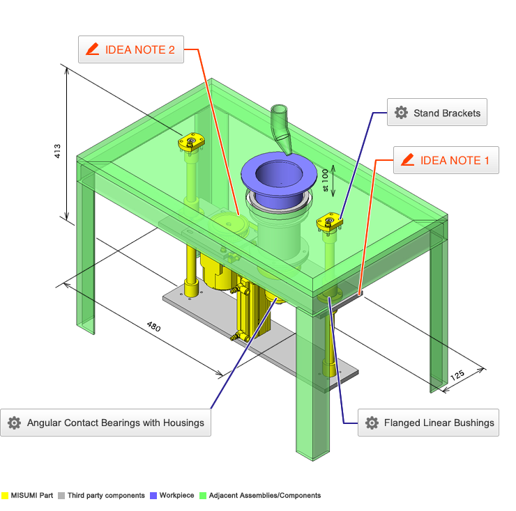
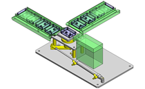
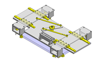
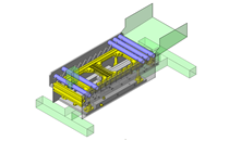
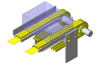
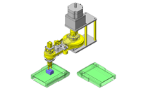
No.000260 Rotating and raising mechanism
35
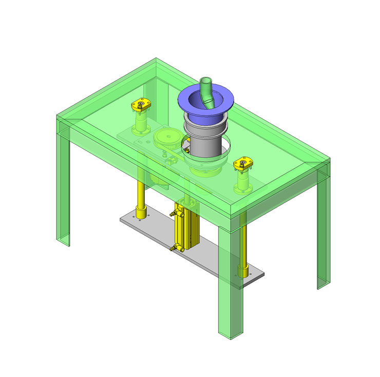
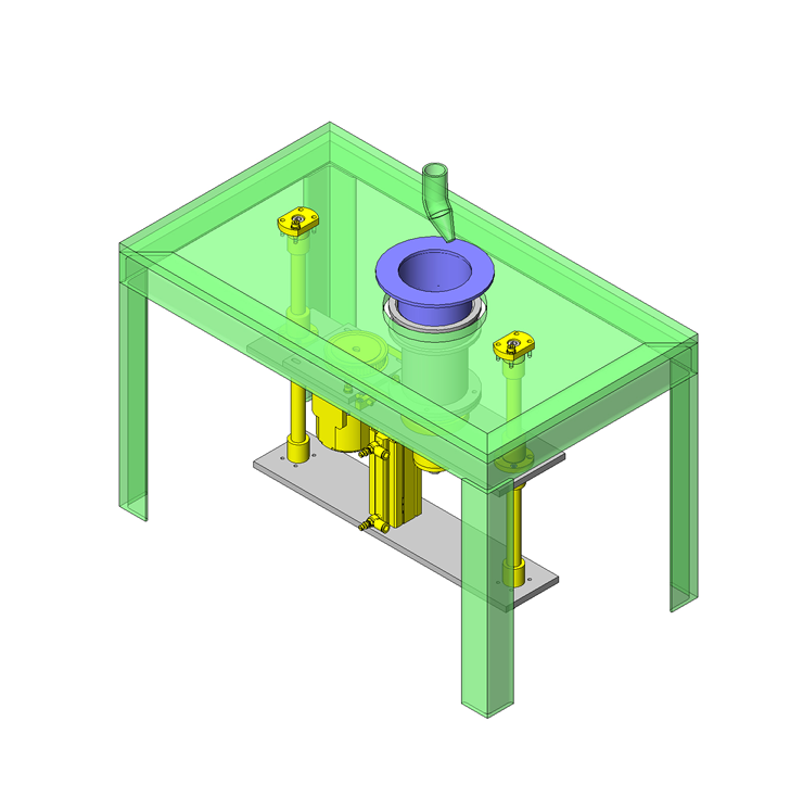
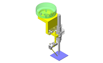
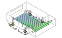
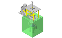
Lifting and rotating mechanism.
Related Category


Angular Contact Bearings with Housings
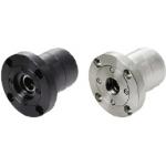
| Product name | Angular Contact/Deep Groove Ball Bearing/Flanged Type |
|---|---|
| Part number | ABGC7004-N-80 |
| Features | Angular Contact Bearings with Housings - Flanged type with Deep Groove Ball Bearings set in Back-to-Back Combination. |
Selection criteria
To handle the changes in work piece weight as well as the durability issues a angular contact bearing is used.
Available sizes
■Angular Contact Bearings with Housings
| (1) Angular Contact Bearings | (3) Holder, (4) Inner Ring Spacer, (5) Standard Cover, (6) Standard Cover, Oil Seal Cover, or O-Ring Cover, (7) Inner Ring Collar | (8) Cover Mounting Screw | ||
|---|---|---|---|---|
| (2) Deep Groove Ball Bearings | ||||
| Material | Material | Surface Treatment | Material | Surface Treatment |
| EN 1.3505 Equiv. | EN 1.1191 Equiv. | Black Oxide | EN 1.7220 Equiv. | Black Oxide |
| Electroless Nickel Plating | EN 1.4301 Equiv. | - | ||
■Sizes and Dimensions
| Bearing No. | Cover Selection | Overall Length | |
|---|---|---|---|
| 7002 | Standard Oil Seal For O-Ring | 60 | 75 |
| 7003 | 70 | 85 | |
| 7004 | 80 | 100 | |
| 7005 | 100 | 125 | |
| 7006 | 120 | 150 | |
| 7007 | 140 | 175 | |
| 7008 | 160 | 200 | |
| 7009 | 180 | 225 | |
| 7010 | 200 | 250 | |

Stand Brackets
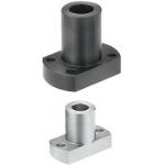
| Product name | Brackets for Device Stands/Tightening from Separate Side/Flanged |
|---|---|
| Part number | PFPM20 |
| Features | Can be fastened from the back side. |
Selection criteria
Select a reversed fastening type to firmly secure the shafts.
Available sizes
■Stand Brackets (Reversed Fastening Type)
| Type | Material | Surface Treatment |
|---|---|---|
| Flange Pilot Flanged | EN 1.1191 Equiv. | Black Oxide |
| Electroless Nickel Plating | ||
| EN 1.4301 Equiv. | - |
■Sizes and Dimensions
| Stand Shaft Bore Dia. | Flange O.D. | Flange Wrench Flats | Overall Length | Post Mounting Screws |
|---|---|---|---|---|
| 6 | 28 | 12 | 16 | M3 |
| 8 | 32 | 15 | 22 | M4 |
| 10 | 38 | 18 | 26 | M5 |
| 12 | 42 | 20 | 32 | M6 |
| 13 | ||||
| 15 | 48 | 32 | 40 | M8 |
| 16 | ||||
| 20 | 55 | 38 | 50 | M10 |
| 25 | 75 | 50 | 62 | M12 |
| 30 | 80 | 55 | 75 | M16 |

Flanged Linear Bushings
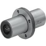
| Product name | Flanged Linear Bushings/Center Flange |
|---|---|
| Part number | LHMRWMF20 |
| Features | A load can be placed near the center of the linear bushing to evenly distribute the load and space. |
Selection criteria
Select a center flanged type so that the plate moving up and down is positioned at the center of the bearing.
Available sizes
■Flanged Linear Bushings (Center Flanged Double Type)
| Type | Outer Cylinder | Ball | Retainer | Operating Ambient Temperature | Accessory | ||
|---|---|---|---|---|---|---|---|
| Material | Hardness | Surface Treatment | Material | Material | |||
| Round Flange Square Flange Compact Flange | EN 1.3505 Equiv. | 58HRC- | - | EN 1.3505 Equiv. | Plastic (Duracon M90 Equiv.) | -20-80°C | Seal: Material Nitrile Rubber (-20 to 120°C) |
| Stainless(SUS) | -20-100°C | ||||||
| Electroless Nickel Plating | EN 1.4125 Equiv. | Plastic (Duracon M90 Equiv.) | -20-80°C | ||||
| Stainless Steel (SUS) | -20-100°C | ||||||
| EN 1.4125 Equiv. | 56HRC- | - | Plastic (Duracon M90 Equiv.) | -20-80°C | |||
| Stainless Steel (SUS) | -20-100°C | ||||||
■Sizes and Dimensions
| I.D. (mm) | Length (mm) |
|---|---|
| 6 | 35 |
| 8 | 45 |
| 10 | 55 |
| 12 | 57 |
| 13 | 61 |
| 16 | 70 |
| 20 | 80 |
| 25 | 112 |
| 30 | 123 |
| 35 | 135 |
| 40 | 151 |
| 50 | 192 |
Selection steps
■Linear Bushing Selection Steps
- Determine conditions of use
- (Loads, Motion pattern, Life hours)
↓
- Temporarily select the specifications of linear bushings
- (Shaft dia. and length are temporarily selected according to the conditions of use.)
↓
- Basic safety check
-
- ●Basic Static Load Rating
- ●Basic Dynamic Load Rating
- ●Allowable Static Moment
- ●Operating Life
↓
- Considerations Based on Required Performance
- ●Life Variations Due to Temperature Changes
Accuracy Info
■Accuracy Info. of Flanged Linear Bushings
(mm)
| I.D. | I.D. Tolerance | Overall Length Tolerance |
|---|---|---|
| 6 | 0 -0.010 | ±0.3 |
| 8 | ||
| 10 | ||
| 12 | ||
| 13 | ||
| 16 | ||
| 20 | 0 -0.012 | |
| 25 | ||
| 30 | ||
| 35 | 0 -0.015 | |
| 40 | ||
| 50 |
Performance info.
■Speeds / Loads (Load Info.) of Flanged Linear Bushings
| I.D. (mm) | Basic Load Rating | |
|---|---|---|
| Basic Dynamic Load Rating (N) | Basic Static Load Rating (N) | |
| 6 | 324 | 529 |
| 8 | 431 | 784 |
| 10 | 588 | 1100 |
| 12 | 657 | 1200 |
| 13 | 813 | 1570 |
| 16 | 1230 | 2350 |
| 20 | 1400 | 2740 |
| 25 | 1560 | 3140 |
| 30 | 2490 | 5490 |
| 35 | 2650 | 6270 |
| 40 | 3430 | 8040 |
| 50 | 6080 | 15900 |
Technical calculations
■Life of Flanged Linear Bushings
When the linear system is loaded in linear reciprocating motion, scaly damages called flaking appear due to material fatigue as the repeated stress is applied on the rolling elements and the rolling contact surfaces constantly. Total travel distance until the first flaking occurs is called the life of linear system.
Rated life can be calculated with the basic dynamic load rating and the actual load applied on the linear bushings, as shown below.
- L: Rated Life (km)
- fH: Hardness Factor (See Fig.1)
- fT: Temperature Factor (See Fig.2)
- fC: Contact Factor (See Table-3)
- fw: Load Factor (See Table-4)
- C: Basic Dynamic Load Rating (N)
- P: Applied Load (N)
●Hardness Factor (fH)
For liner system applications, sufficient hardness is required for ball contact shafts. Inappropriate hardness causes less allowable load, resulting in shorter life.
Fig. 1. Hardness Factor
●Temperature Factor (fT)
When the temperature of linear system exceeds 100°C, the hardness of the system and shafts will be reduced and the allowable loads will also be reduced compared to being used at room temperature, resulting in a shorter life.
Fig. 2. Temperature Factor
●Contact Factor (fC)
More than two linear systems are used for one shaft in general. In this case, the load applied to each linear system varies depending on machining precision and is not uniformly distributed. As a result, allowable load per linear system changes depending on the number of linear systems used on one shaft.
Table-3. Contact Factor
| Number of Bearings Installed on One Shaft | Contact Factor fC | |
|---|---|---|
| 1 | 1 | |
| 2 | 0.81 | |
| 3 | 0.72 | |
| 4 | 0.66 | |
| 5 | 0.61 | |
●Load Factor (fW)
To calculate load applied to the linear system, in addition to object weight, it requires inertia force attributed to motion velocity or moment loads. Further, it is necessary to accurately determine the temporal change of each. However, it is difficult to calculation the load accurately due to potential vibrations and shocks caused by other element than repeated start-stop motions during reciprocating motion. Therefore, use the table below in order to simplify the life calculations.
| Conditions of Use | fw |
|---|---|
| No external shocks or vibrations and speed is low 15m/min or less | 1.0 ~ 1.5 |
| No significant shocks or vibration and med. speed 60m/min or less | 1.5 ~ 2.0 |
| External shocks and vibrations exist and the speed is high 60m/min or over | 2.0 ~ 3.5 |
Life in hours can be obtained by calculating the travel distance per hour. When the stroke length and the number of strokes are constant, it can be calculated using the formula below.
- Lh: Life (Hr.)
- L: Rated Life (km)
- Ls: Stroke length (m)
- n1: Number of Cycles per Minute (cpm)


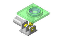
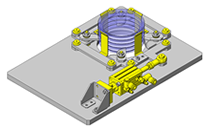
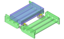
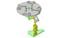
IDEA NOTE Rotates workpieces with timing pulley
By mounting a work piece receiving plate just above the driven side of the pulley, and held with a double rowed angular contact bearing, the work piece weight against the motor and accuracy are improved.


-

-
 Terms of use of CAD data and simplified drawing data
- These terms and conditions (hereinafter referred to as “the Terms") set forth the conditions for downloading CAD data and simplified drawing data provided by MISUMI Corporation (hereinafter referred to as "MISUMI") via www.misumi-europe.com operated by MISUMI Europa GmbH(hereinafter referred to as the "Website"). By downloading CAD data and simplified drawing data posted on the Website (hereafter referred to as “Data”), customers are deemed to have agreed to these Terms.
- 1. Purpose of Use
-
MISUMI offers the following:
1)CAD data found on the Website (3D CAD data, 3D Intermediate data and 2D CAD data) for the purpose of informing customers of the characteristics of the products offered by MISUMI or a manufacturer affiliated with MISUMI for use in their designs.
2)Simplified drawing data (in PDF format) for the purpose of checking the specifications of products. - 2. Characteristics of Data
- There may be a discrepancy in certain characteristics of products (for example: tolerance, surface roughness, chamfer, etc.) between the Data and the actual product. Furthermore, for the purpose of reducing the file size of the Data, some information such as oil groove shapes, threads, or spring shapes, may be removed from the Data.
- 3. Disclaimer
- MISUMI carefully creates the Data but makes no warranty as to the quality, accuracy, functionality, safety, reliability, etc., of the Data. MISUMI may at any time, and with no prior notice to customers, revise or delete Data. MISUMI assumes no responsibility for any damage or loss resulting from any revision or deletion of the Data, or any errors in said data. Customers are solely responsible for all aspects of their own designs, including those made using the Data. MISUMI may provide customers with design example data on the Website, but the quality, accuracy, functionality, safety, reliability, etc., of such data are not guaranteed. MISUMI may, at any time, and in its sole discretion, request that the customer cease its use of or destroy the Data in its possession. MISUMI may request the customer provide MISUMI documentation of such destruction.
- 4.Prohibited Acts
-
Customers or users of the Data, are prohibited from the following acts regarding the Data, in whole or in part:
(1)Requesting quotations or placing orders for products with third parties other than those authorized by MISUMI or its affiliates;
(2)Receiving quotations or orders for products from third parties by providing the Data to a third party or using the Data in their own business;
(3)Displaying links to the Website related to the Data on their own websites, etc., without consent of MISUMI or its affiliates;
(4)Using or reproducing the Data beyond the scope of the above-stated Purpose of Use;
(5)Modifying, altering, tampering with, translating, or adapting the Data;
(6)Selling, transferring, lending, sublicensing, or providing the Data to third parties in any way without consent of MISUMI or its affiliates;
(7)Altering the content, reverse engineering, decompiling, disassembling, or analyzing the Data;
(8)Publicly disclosing or exhibiting the Data without consent of MISUMI or its affiliates;
(9)Using the Data for the purpose of providing products and services identical or similar to those of MISUMI or its affiliates;
(10)Performing acts that interfere with the proper functioning of this Website, such as acquiring Data in bulk. - 5. Copyright
-
All title and copyright in and to any information contained in the Data are owned by MISUMI or the relevant manufacturer affiliated with MISUMI and are protected by applicable copyright laws and international treaties. By downloading Data, the customer acquires no ownership rights of any kind in the intellectual property contained within. Without prior approval from MISUMI, no part of the Data may be utilized (reproduced, modified, reverse-engineered, uploaded, presented, sent, distributed, licensed, sold, or published) for any purpose other than that mentioned above.
In the event Data is found to have been to be used for any purpose other than that mentioned above or against any applicable laws or the Terms, MISUMI may pursue any legal remedy available to it, which may result in forbidding the offending user from using the Data or accessing the Website. - 6. Third-Party Data
- MISUMI offers some Data provided by third parties. Such Data may be subject to separate terms and conditions, in addition to these terms. MISUMI makes no guarantee or warranty regarding Data from third parties.
- 7. Export Control
- Customers shall comply with all applicable laws and regulations regarding the export of the Data.
- 8. Amendments to the Terms
- MISUMI may, at any time, and in its sole discretion, modify these terms and conditions; any such modification will be effective immediately.
- 9. Severability
- If any term or provision of these Terms is invalid, illegal, or unenforceable in any jurisdiction, such invalidity, illegality, or unenforceability shall not affect any other term or provision of these Terms or invalidate or render unenforceable such term or provision in any other jurisdiction. Section 139 BGB (German Civil Code) shall not apply.
- 10.Miscellaneous
-
In the event that Customers violate the Terms, MISUMI and/or MISUMI Europa GmbH shall be entitled to claim the damages and expenses (including attorney's fees) incurred by such violation against the Customers.
These Terms and any disputes arising in connection therewith shall be exclusively governed by and construed in accordance with the laws of the Federal Republic of Germany, without regard to its conflicts of law principles. The courts located in Frankfurt am Main/Germany shall have exclusive jurisdiction to adjudicate any dispute arising in connection with these Terms. By downloading the Data, you agree to submit to the exclusive and personal jurisdiction of the courts located in Frankfurt am Main/Germany. - Revised: September 21, 2025
CAD Data Download (Unit Assembly)
CAD Data Download: File Format
Cautions on the CAD data
-
Assembly data shows the assembly drawings in the concept design phase. The sole purpose of the data is to explain the structure and functionality of the assembly and is not considered nor to be used as a final design.
You will need to edit the Data so that it meets your specific design conditions. -
The CAD data unit assembly consists of sub-assemblies.
Each sub-assembly unit can be used as it is or can be edited. - The Data for fabricated parts is based on easy-to-edit dimensions and shapes in sketches and histories.
- The Data including the third-part components are made by the Company.
* The part in the frame is a sub-assembly unit.
-

- * Unit assembly CAD data consists of some sub-assemblies.
Each sub-assembly unit can be used as it is or can be edited.
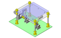
Application Overview
Purpose
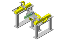
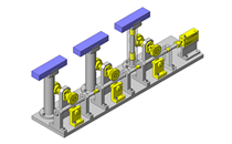
- Simplified multiple movement mechanism.
Points for use
- Blower included within the cylindrical thin plastic work pieces serves as a cleaning mechanism.
- The work piece is raised into the fixed blower, at this point through the rotation and movement cleaning can be implemented from all angles of the work piece.
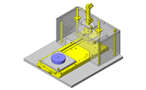
Target workpiece
- Long cylindrical workpiece.
- External dimension: Ø160 x H90mm
- Workpiece weight: 219g
Design Specifications
Operating Conditions or Design Requirements
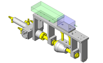
- Specifications for workpiece operation
- Rotating angle: 360deg; Rotational speed: 0.5rev/sec = 3.14rad/sec
- Elevation stroke: 100mm; Elevation velocity: 100mm/sec
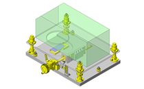
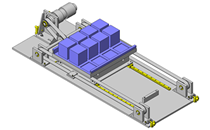
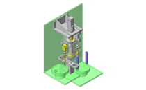
- Equipment dimensions
- External dimensions: W480 x D125 x H413mm
- Depth of underneath the table: 408mm
Required Performance
- Specifications for workpiece operation
- Rotation start time: 0.1sec
- Elevation start time: 0.1sec
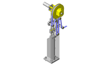
Selection Criteria for Main Components
- Rotational torque of motor gear head.
- Thrust of cylinder.
Design Evaluation
Verification of main components
- Verification of the motor torque and cylindrical thrust required below.
- Rotational torque of motor gear head (60Hz)
- Rated rotational speed of motor: 1575 [Hz]→Gear head reduction ratio: (1575/60)/0.5 = 52.5 → 50 is adopted
- Starting torque of motor: 0.17N・m →Gear head conversion: 0.17 x 50 = 8.5N・m
- Allowable torque of gear head: 5.29N・m (from catalog) < 8.5 →5.29N・m is adopted
- Total inertia of rotating part: J = 6083kg・mm² = 6083 x 10-6kg・m²
- Rotation start time: 0.1sec → Rotation start angular acceleration: dω/dt = 3.14 / 0.1 = 31.4rad/sec²
- Required torque of rotating part: Tr = dω/dt x J = 31.4 x 6083 x 10-6 = 0.191N・m
- Belt overload coefficient Ks = 1.6 (catalog value), Required torque of driving side: 0.191 x 1.6 = 0.306N・m
- Safety factor: 5.29/0.306 = 17.3
- Thrust of cylinder
- Total weight of elevating part: 10.68kg, Acceleration for vertical push: g + dv/dt = 9.8 + 1 = 10.8m/sec²
- Required thrust of cylinder: F = 10.68 x 10.8 = 115.5N
- Operating pressure: 0.5MPa; Theoretical output of push side: 628N (from catalog)
- Safety factor: 628/115.5 = 5.44
- Specifications for workpiece operation
- Elevation start time: 0.1sec → Elevation start acceleration: dv/dt = 100 / 0.1 = 1000mm/sec² = 1m/sec²
Other Design Consideration
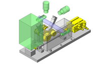
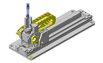
- Through the use of a timing pulley, the accuracy of the work piece angle can be improved.
- By separating the motor gear head and the rotating portion of the work piece, the overhang load of the gear head can be avoided.
Explore Similar Application Examples


Payment Method


On-Demand Manufacturing
Certificates


Copyright © MISUMI Corporation All Rights Reserved.