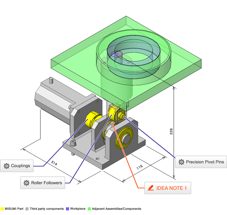
Couplings
* Orange colored cells in the table below indicate the part numbers used in this example.
Selection criteria
Shorter length and good declination performance
Back to page top
Available sizes
■Couplings - Slit, Clamping
| Material | Surface Treatment | Accessory |
| Alum. Alloy | Anodized | Hex Socket Head Cap Screw |
| Stainless Steel | - |
■Sizes and Dimensions
| O.D. (mm) | Shaft bore Dia. (mm),
Driving Side | Shaft bore Dia. (mm),
Driven Side | Overall Length (mm) | Set
Screw |
| Standard Type | Short |
| Ø12 | *4 | *4, *5 | 18.5 | 14 | M2 |
| *5 | *5 |
| Ø16 | *5 | *5, *6 | 23 | 18 | M2.5 |
| *6 | *6 |
| Ø20 | *5 | *6, 6.35, *8 | 26 | 20 |
| *6 | *6, 6.35, 7, *8 |
| 6.35 | 8 |
| *8 | *8 |
| Ø25 | *5 | *6 | 31 | 25 | M3 |
| *6 | *6, 6.35, *8, *10 |
| 6.35 | 8, 10 |
| *8 | *8, 9.525, *10 |
| 9.525 | 10 |
| *10 | *10 |
| Ø32 | *8 | *8, 9.525, *10, 12 | 41 | 32 | M4 |
| 9.525 | 10, 12 |
| *10 | *10, 11, *12, 14 |
| *12 | *12, *14 |
| Ø40 | 8 | 8, 10 | 56 | - | M5 |
| 10 | 10 |
| 12 | 12, 14 |
| 14 | 14, 16 |
| 15 | 15 |
| 16 | 16 |
Short type is available for sizes marked with * only.
Back to page top
Accuracy Info
■Accuracy of coupling
| Type | O.D. (mm) | Shaft Bore Tolerance | Allowable Angular Misalignment
(°) | Lateral Misalignment
(mm) |
|
|
| Standard | Ø12 | +0.5 for the same Dia.
Larger for different Dia.
Shaft Dia. +0.5, see | 2 | 0.10 |
| Ø16 |
| Ø20 |
| Ø25 | 0.15 |
| Ø32 |
| Ø40 | 0.20 |
| Short | Ø12 | 1 | - |
| Ø16 |
| Ø20 |
| Ø25 |
| Ø32 |
The shaft Dia. tolerance represents the tolerance before slit machining.
Back to page top
Performance info.
■Load info. on coupling
| Type | O.D. | Allowable Torque
(N・m) | Max. Rotational Speed
(r/min) | Moment of Inertia
(kg・m²) |
|
Aluminum
normal | Ø12 | 0.4 | 52000 | 7.8 x 10 -8 |
| Ø16 | 0.5 | 39000 | 3.4 x 10 -7 |
| Ø20 | 1 | 31000 | 9.1 x 10 -7 |
| Ø25 | 2 | 25000 | 2.6 x 10 -6 |
| Ø32 | 4 | 19000 | 9.7 x 10 -6 |
| Ø40 | 8 | 15000 | 3.3 x 10 -5 |
Stainless
Steel Normal | Ø12 | 0.3 | 52000 | 2.2 x 10 -7 |
| Ø16 | 0.5 | 39000 | 9.0 x 10 -7 |
| Ø20 | 1 | 31000 | 2.5 x 10 -6 |
| Ø25 | 2 | 25000 | 7.1 x 10 6 |
| Ø32 | 3.5 | 19000 | 2.7 x 10 -5 |
| Ø40 | 8 | 15000 | 9.0 x 10 -5 |
Aluminum
Short | Ø12 | 0.4 | 52000 | 6.4 x 10 -8 |
| Ø16 | 0.5 | 39000 | 2.9 x 10 -7 |
| Ø20 | 1 | 31000 | 7.5 x 10 -7 |
| Ø25 | 2 | 25000 | 2.3 x 10 -6 |
| Ø32 | 4 | 19000 | 8.1 x 10 -6 |
Stainless
Steel Short | Ø12 | 0.3 | 52000 | 1.8 x 10 -7 |
| Ø16 | 0.5 | 39000 | 7.8 x 10 -7 |
| Ø20 | 1 | 31000 | 2.1 x 10 -6 |
| Ø25 | 2 | 25000 | 6.3 x 10 -6 |
| Ø32 | 3.5 | 19000 | 2.2 x 10 -5 |
Back to page top
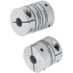
Roller Followers
| Product name | Roller Followers/Separate/Flat Type |
| Part number | NASTFZS12 |
* Orange colored cells in the table below indicate the part numbers used in this example.
Selection criteria
Effective as a cam follower to convert circular motion to linear reciprocating motion
Back to page top
Available sizes
■Roller Followers - Separate
| Grease | No Seal | With Seal | Material |
| Crowned | Flat Type | Crowned | Flat Type |
| General | ○ | ○ | ○ | ○ | EN 1.3505 Equiv. |
| - | ○ | ○ | ○ | EN 1.4125 Equiv. |
| Low Particle Generation | - | - | - | ○ |
■Sizes and Dimensions
O.D.
(mm) | I.D.
(mm) | Thickness (mm) |
| No Seal | With Seal |
| 19 | 6 | 9.8 | 13.8 |
| 24 | 8 |
| 30 | 10 | 11.8 | 15.8 |
| 32 | 12 |
| 35 | 15 |
| 40 | 17 | 15.8 | 19.8 |
| 47 | 20 |
Back to page top
Accuracy Info
■Accuracy Information of Roller Followers
- Shaft Dia. Tolerance:
- 0
-0.008(mm)
- Roller Dia. Tolerance:
- 0
-0.005(mm)
Back to page top
Performance info.
■Speeds・Loads (Load info.) of roller followers
I.D.
- O.D. | Basic Dynamic Load Rating C (kN) | Basic Static Load Rating Cor (kN) | Max. Allowable Load (kN) | Track Load Capacity (kN) | Max. Rotational Speed (rpm) |
| No Seal | With Seal |
| Crowned | Flat
Type | Crowned | Flat
Type | No Seal | With Seal |
| Ø6-Ø19 | 4.12 | 4.55 | 0.36 | 1.37 | 3.53 | 1.37 | 3.53 | 20000 | 8000 |
| Ø8-Ø24 | 5.68 | 5.89 | 0.78 | 1.86 | 4.02 | 1.86 | 4.51 | 17000 | 6800 |
| Ø10-Ø30 | 9.7 | 9.67 | 1.42 | 2.45 | 5.59 | 2.45 | 6.86 | 15000 | 6000 |
| Ø12-Ø32 | 10.4 | 10.9 | 2.11 | 2.74 | 5.98 | 2.74 | 7.35 | 13000 | 5200 |
| Ø15-Ø35 | 12.3 | 14.3 | 4.73 | 3.14 | - | - | 8.04 | 10000 | 4000 |
| Ø17-Ø40 | 17.4 | 20.9 | 5.81 | 3.72 | 11.8 | 9500 | 3800 |
| Ø20-Ø47 | 19.2 | 24.5 | | 4.61 | 13.8 | 8500 | 3400 |
Back to page top
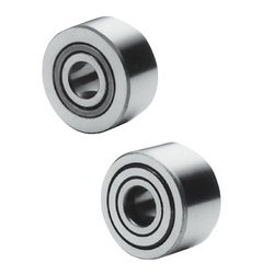
Precision Pivot Pins
| Product name | Precision Pivot Pins/Straight/Retaining Rings |
| Part number | SCCG12-28 |
* Orange colored cells in the table below indicate the part numbers used in this example.
Selection criteria
Effective as the roller shaft of a cam follower
Back to page top
Available sizes
■Precision Pivot Pins - Straight, Retaining Rings
| Material | Hardness | Surface Treatment | Accessory |
|
| EN 1.1191 Equiv. | - | Black Oxide | Retaining Ring 2 pc. | Spring Steel |
| 40 - 45 HRC |
| - | Electroless Nickel Plating | EN 1.4301 Equiv. |
| 40 - 45 HRC |
| Plating hardness 750 HV - | Hard Chrome Plating | Spring Steel |
| plating thickness 3 μm or more |
| EN 1.4301 Equiv. | - | - | EN 1.4301 Equiv. |
| EN 1.4125 Equiv. | 45 - 50 HRC |
| 45 - 50 HRC | Hard Chrome Plating |
| Plating hardness 750 HV - | plating thickness 3 μm or more |
■Sizes and Dimensions
| Pin Dia. | Pin Section Length |
| (Configure in 0.1mm increment) |
| Ø2 | 5.0-30.0 |
| Ø3 | 5.0-50.0 |
| Ø4 |
| Ø5 | 10.0-60.0 |
| Ø6 | 10.0-100.0 |
| Ø8 |
| Ø10 | 15.0-100.0 |
| Ø12 | 15.0-200.0 |
| Ø13 | 25.0-200.0 |
| Ø14 |
| Ø15 |
| Ø16 | 30.0-200.0 |
| Ø17 |
| Ø18 |
| Ø20 |
| Ø22 |
| Ø25 |
Back to page top
Accuracy Info
■Pivot pin Dia. Tolerance (g6) for Hinge Pin Straight Retaining Ring Type
| Pin Dia. | Tolerance |
| Ø2 ・ Ø3 | -0.002
-0.008 |
|
| Ø4-Ø6 | -0.004
-0.012 |
|
| Ø8 ・ Ø10 | -0.005
-0.014 |
|
| Ø12-Ø18 | -0.006
-0.017 |
|
| Ø20-Ø25 | -0.007
-0.020 |
|
Back to page top
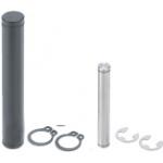
IDEA NOTE The load cell is moved up and down by a cam.
The cam causes the load cell to stroke 1.5mm. As the load is applied to the bearing of the cam shaft, the load is not applied to the vertical movement mechanism.


